I looked into the operation of RoCE v2 1, a mechanism that realizes RDMA over Ethernet, within Microsoft.
Introduction
When it comes to RDMA, I had the image of Infiniband, but recently iWARP and RoCE are also candidates. RoCE stands for Remote Direct Memory Access over Converged Ethernet. Remote Direct Memory Access is a mechanism that can read and write the main memory of a remote node without going through the CPU. I understood Converged Ethernet as lossless Ethernet. RoCE has two versions, v1 and v2. v1 has a structure where the RDMA payload is placed after the L2 header. It fundamentally assumes RDMA between L2 subnets. On the other hand, v2 has the RDMA payload placed after the L4 header. In other words, since it’s a protocol on Ethernet/IP/UDP, it can realize RDMA via IP routing.
Why is RDMA needed in data centers in the first place? I think it’s because demands that the TCP/IP stack cannot satisfy have emerged. For example, looking at CPU utilization in 40Gbps/8 session communication, it’s 8% on the transmission side and 12% on the reception side. Reducing this overhead is the aim of RDMA introduction. Latency reduction is also often an aim. Since the network stack of end nodes is implemented in software (Linux kernel, etc.), there is fundamentally room for latency to creep in (such as waiting for scheduling). Also, TCP/IP performs congestion control assuming packet drops will occur, which is also a cause of latency.
This time, we realize RDMA on an IP CLOS network. Almost all links are 40G, and all switches handle IP routing. RoCE v2 has a 5-tuple, so it can benefit from ECMP (Equal Cost Multipath Routing). In lossless networks, packet loss due to buffer overflow etc. at switches in the communication path must not occur. Therefore, PFC (Priority-based Flow Control) is used to control flow rate. PFC is a link-to-link protocol, and when switch buffer utilization exceeds a certain threshold, it sends a pause frame to the link partner switch. The pause frame has the meaning of requesting packet transmission to stop. Since Priority can be assigned to each queue, pause frames can be sent per queue. However, since there is a time lag between sending the pause frame and actually stopping transmission, margin is maintained. Within Microsoft, switches have Shallow Buffer, so only two Priorities are used. One is used for latency-oriented real-time traffic, and the other for bandwidth-oriented bulk data traffic. Since PFC is a link-to-link protocol, it propagates through switches several times before reaching RDMA endpoints. Therefore, it’s used in combination with DCQCN (Data Center Quantized Congestion Notification), which is an end-to-end protocol.
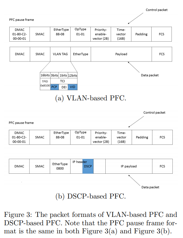
There are two types of PFC protocol specifications depending on which header the Priority is set in. Originally, it was a VLAN-based specification where Priority is set in the VLAN tag. However, it didn’t work well with IP CLOS networks assuming IP routing or with PXE boot. Therefore, a DSCP-based specification emerged where Priority is set in the IP header’s DSCP. Within Microsoft, PFC Priority is simply assigned as the DSCP value. Currently, major switch vendors support DSCP-based.
Issues
Even in lossless networks, packet loss cannot be completely prevented. Examples include FCS (Frame Check Sequence) and software bugs as causes. As an experiment, when packet loss was caused with a 0.4% (1/256) probability, the link showed wire rate, but from the application’s perspective there was no progress at all. This was due to the specification that when a packet is dropped, retransmission occurs from the first packet. As a countermeasure, it was changed to retransmit from the packet where the drop was detected (go-back-N).
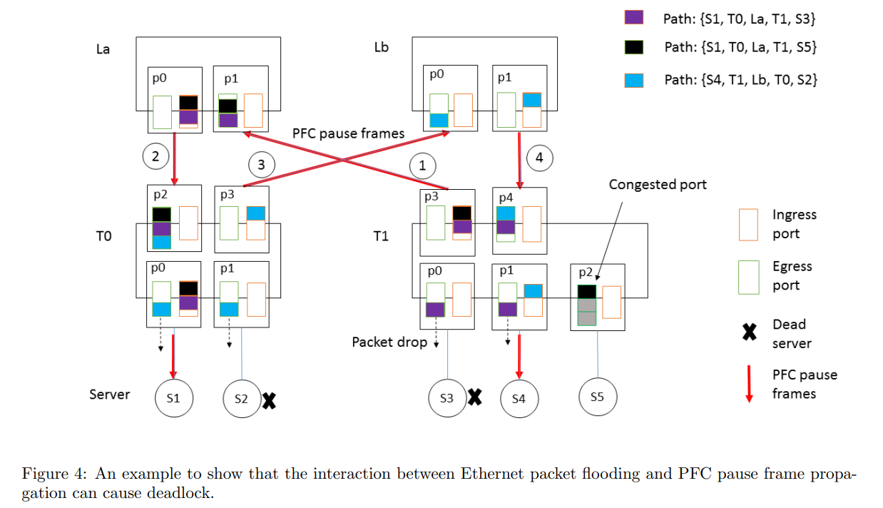
In CLOS topology, packets follow the path ToR-Leaf-Spine-Leaf-ToR, so there is no circular dependency of buffers, and deadlock was expected not to occur in principle. Here, circular dependency of buffers means that when all buffers are saturated and they depend on each other, no buffer can send out data. As a premise, servers under the ToR belong to the same subnet. Also, when ToR receives a packet, it references the ARP table and MAC address table. Note that the ARP table is CPU-processed so the cache period is 4 hours, while the MAC address table is hardware-processed so the cache period is 5 minutes. This difference in cache periods causes circular dependency. When an entry exists in the ARP table but no entry exists in the MAC address table, unicast flooding sends the packet from all ports except the receiving port. In other words, the assumption of the ToR-Leaf-Spine-Leaf-ToR path breaks down, and circulation occurs. Furthermore, when combined with PFC, it leads to deadlock. As a countermeasure, in lossless networks, packets were dropped instead of flooding. Be careful as broadcast and multicast use in lossless networks is dangerous.
There was a bug in the NIC’s receive queue that kept sending PFC pause frames. Since PFC pause frames spread across the entire network, the impact range is large. Therefore, a watchdog was implemented in the NIC and ToR.
It was assumed that congestion would not occur within the server since Server-ToR is 40Gbps and Server internal PCIe Gen3 x8 is 64Gbps. However, due to insufficient entries in the NIC’s MTT (Memory Transaction Table), access occurred between NIC and main memory, and buffers accumulated due to that latency. It was addressed by increasing page size.
Operations
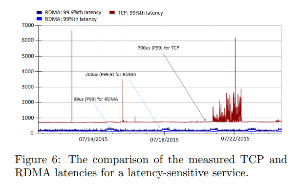
The number of PFC pause frames transmitted and received per switch is aggregated. They wanted to get the paused period per server from the switch, but currently cannot, so they are coordinating with vendors. For continuous latency measurement, RDMA Pingmesh was introduced. They transfer 512 bytes of data via RDMA to servers placed in different locations and measure RTT and failure reasons. Looking at latency in actual low-throughput situations, it was lower latency compared to TCP environments. Even at the 99.9 percentile, bursty latency did not occur. However, when high throughput was produced, latency degraded to TCP environment levels. In other words, RDMA does not simultaneously satisfy high throughput and low latency.
Summary
RoCE v2 was deployed at large scale in the data center. Also, DSCP-based PFC was proposed. In the future, we want to work on inter-data center RDMA, and applying RDMA to ideas like Multi-path TCP and Per-Packet Routing.