I read Facebook’s paper 1 from NSDI 2021 and tried to summarize it in my own words without fear of mistakes.
Overview
This is a summary of Facebook’s BGP-based data center network. It covers practical content such as AS number allocation, route aggregation, BGP policies, testing and deployment methods for custom BGP implementations. The latter part also touches on actual incidents experienced over the past two years of operation.
1 Introduction
Facebook operates several data centers, and these data centers have a common AS number allocation schema. That is, switches in data center B that correspond to switches in data center A have the same private AS numbers. They run BGP agents on a large number of switches and adopt a Clos topology with a hierarchical structure overall, performing route aggregation at all layers to keep the hardware FIB to a minimum. BGP is a technology originally used on the Internet, and throughout its history has experienced convergence issues, route instability, and accidents due to misconfigurations. However, when applying it to data centers, operators can manage and operate all switches, allowing flexible response to these problems. For example, for communication failures, by having backup routes in advance, even if a link or switch fails, the failure can be quickly converged by limiting the range where the failure propagates. Furthermore, aiming for a minimal implementation with a faster development cycle than vendor BGP agents, Facebook is developing its own BGP agent in-house.
2 Routing Design
The goal is to build a scalable network, but it also needs to be built in a short time. Also, no matter how much availability is pursued, accidents will happen, so we want to reduce their impact by design. At that time, deploying a routing design using BGP was superior in both speed and track record compared to developing centralized SDN. They originally used vendor switches and their BGP implementations, but later developed their own hardware and BGP agent implementation.
They considered IGP protocols like OSPF and ISIS as routing protocols, but their scalability was unclear and it didn’t seem possible to control route propagation. They also considered hybrid routing designs combining BGP and IGP, but operational costs would be high, so they finally decided to adopt BGP as the only routing protocol.
2.1 Topology Design
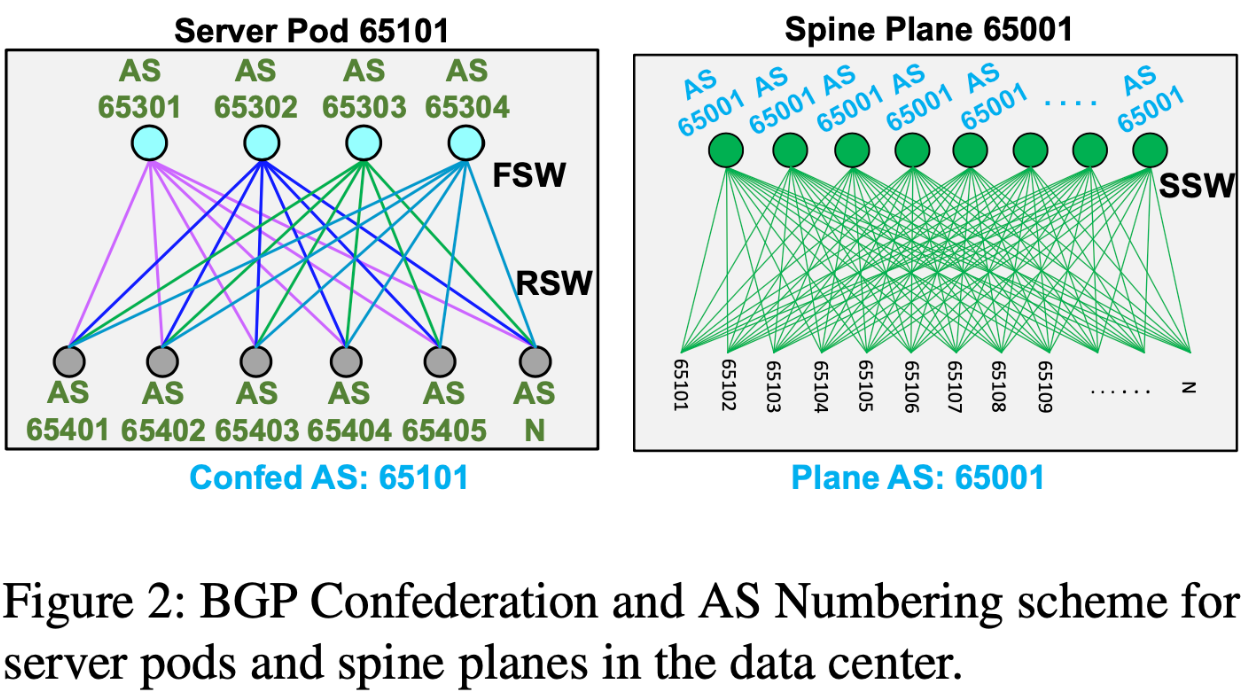
The data center is designed with a collection of racks called server pods as modules, which are aggregated by Spine Planes. The topology can be understood from the figure below, but I’ll describe it in words as well. One server pod consists of 48 server racks, connected to 16 FSWs. Server pods are interconnected via multiple Spine Planes. The number of Spine Planes themselves is equal to the number of FSWs deployed in one server pod (four in the figure below: blue, yellow, green, purple). Bandwidth can be increased by adding links between Spine Planes and server pods. That is, compute resources can be increased by adding server pods, and network resources can be increased by adding SSWs.
 Source:
 2.2 Routing Design Principles
The two main pillars are seeking uniformity and simplicity. To achieve these, they minimize the Feature Set used in BGP and strive to apply the same configuration to multiple switches as much as possible. Within the same Tier (RSW, FSW, SSW), they apply the same configuration except for the prefix to originate and BGP peer addresses. Also, to remove vendor dependencies, they create network topology data in a platform-independent form. This data includes port maps, IP address assignments, BGP configuration, and routing policies. A system called Robotron 2 automatically converts it to platform-specific configurations.
2.3 BGP Peering and Load Balancing
Peering is done only with directly connected 1-hop eBGP sessions. Multihop is not used. When a switch has multiple links, each is treated as an individual eBGP session. Load balancing is realized by ECMP. Due to the route aggregation and routing policy mechanisms described later, FIB updates accompanying next hop additions/deletions when failures occur and are recovered are lightweight, and operations have become simple. For simplicity, per-route weighting is not performed.
2.4 AS Assignment
AS assignment is the same across all data centers. For example, if AS65001 is assigned to the first SSW in one data center, the same AS number is reused in another data center. A server pod is assigned an AS number that identifies itself, and it is identified by this AS number from outside the server pod. That is, the AS numbers of switches within the server pod (RSW, FSW) are confined within that server pod. Due to this property, the AS numbers of RSW and FSW are reused across all server pods. Spine Planes are assigned unique AS numbers within the data center. A Spine Plane consists of multiple SSWs, but these SSWs have the same AS number (they can be shared because there are no peer connections between SSWs).
 Source:
 2.5 Route Aggregation
Route aggregation is performed hierarchically at all tiers. For example, RSWs aggregate IPs of servers under them, and FSWs aggregate routes of RSWs under them. Through route aggregation, hundreds of thousands of routes can be drastically reduced to thousands of routes.
3 Routing Policy
By using BGP, we can benefit from high availability through best path selection. Furthermore, since we can intervene in route advertisement, we can precisely control propagation.
3.1 Policy Goals
We want to achieve four items: reliability, maintainability, scalability, and service reachability.
- Reliability
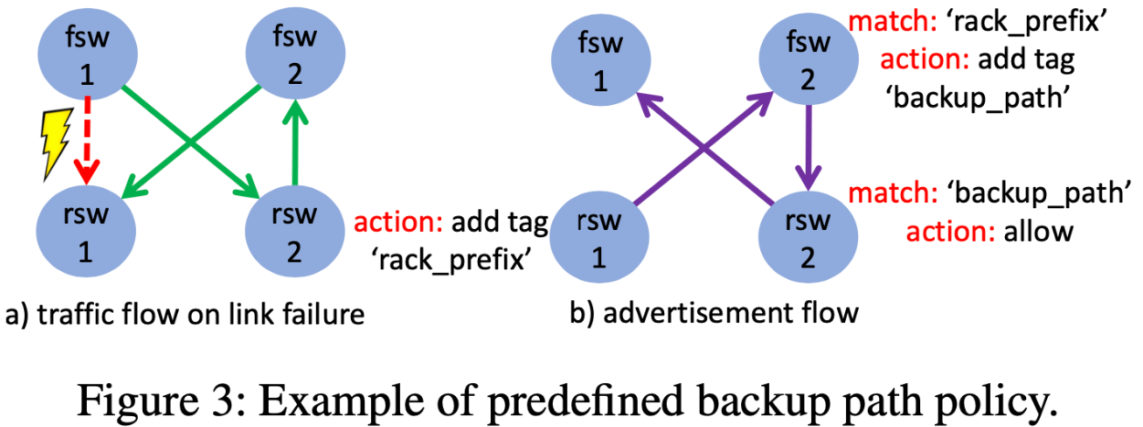
- Limit the scope of route propagation and define backup routes in advance. Backup routes are like FSW1->RSW2->FSW2->RSW1, and are propagated in a scope confined to the server pod with BGP community tags attached in advance. With backup routes, even if a link goes down, the service can continue. Due to the property that propagation is confined to the server pod, convergence time is short and there is no impact on other server pods. Also, in reality, there are multiple backup routes due to ECMP, so the load is distributed.
- Maintainability
- Switches have three types of states: LIVE, DRAINED, and WARM, rather than just two types like up/down. WARM corresponds to a state where RIB and FIB are ready, but traffic is not flowing. By having these three states, they perform an average of 242 operations per day without packet drops.
- Scalability
- Since FSWs aggregate rack-level prefixes, the increase in route count due to server pod additions is small and scalable.
- Service Reachability
- Services are provided via VIP, and that VIP is advertised by BGP from multiple instances. For advertisement, instances directly establish BGP sessions with RSWs.
 Source:
 3.2 Policy Configuration
They apply 3-11 policies for inbound and 1-23 policies for outbound.
3.3 Policy Changes
Very stable with only 40 commits of changes over the past 3 years. Breaking it down, over 80% of commits were small-scale, changing less than 2% of total lines.
4 Comparison of BGP in Data Centers and the Internet
BGP convergence, instability, and misconfiguration have been discussed for a long time in the Internet context. Here we summarize in the data center context.
4.1 BGP Convergence
On the Internet, it’s known that BGP convergence takes several minutes (Path Hunting problem). Also, in the worst case, O(n!) messages are sent where n is the number of routers. In data centers, by limiting the scope of BGP advertisement, the number of messages can be drastically reduced. The MIRAI timer that controls message transmission intervals is set to 0 seconds, aiming for the fastest convergence.
4.2 Route Instability
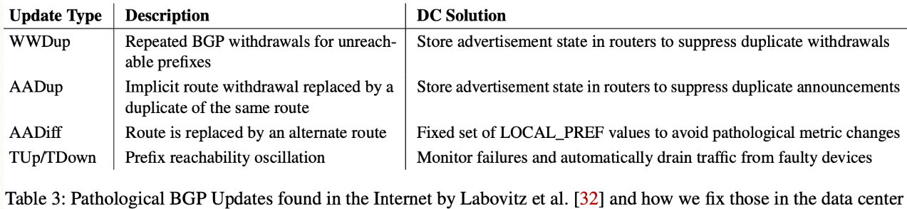
A large number of BGP Update messages causes router CPU and memory exhaustion, leading to slow convergence and packet loss. Causes of instability include WWDup, AADup, AADiff, Tup/TDown (needs review).
 Source:
 4.3 BGP Misconfiguration
Two types of mistakes can occur: incorrect originating prefixes and incorrect AS_PATH, but they are prevented by automation tools and monitoring.
5 Software Implementation
It was difficult to add new features to existing BGP implementations, and the development cycle was long, making them unsuitable for application in Facebook’s data centers. Therefore, they developed their own BGP agent in C++ that runs on FBOSS switches. They satisfied RFCs while making a minimal implementation limited to use within data centers. By supporting multithreading (Quagga and Bird are single-threaded), convergence time was reduced by 1.7-2.3 times compared to Quagga and Bird.
Vendor BGP implementations cannot establish multiple BGP sessions from the same peer address, making it difficult to advertise VIPs for applications. Therefore, they removed this restriction, allowing applications to directly establish BGP sessions to RSWs. Since no Injector within the server is involved, operational costs were reduced.
6 Testing and Deployment
Testing and deployment targets are two things: BGP configuration and agent implementation itself.
6.1 Testing
Testing consists largely of unit tests, emulation, and canary tests. Emulation is a very useful tool, testing by mimicking the entire network based on BGP configuration and policies. It’s also useful for mimicking events like link flaps, link downs, and BGP restarts. However, since emulation on Linux containers is slower than hardware switches, experimenting with BGP convergence time itself became a challenging topic.
6.2 Deployment
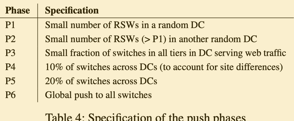
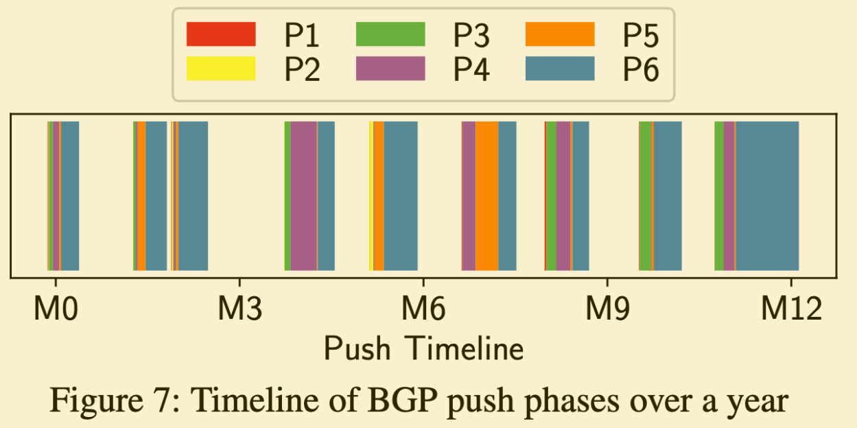
They adopt rolling updates that update gradually, while wanting to detect problems early. First, all changes are classified as either disruptive or non-disruptive based on whether they change packet forwarding state. For non-disruptive cases, they deploy using BGP Graceful Update mechanism while keeping routes unchanged. On the other hand, for disruptive changes, since route addition/deletion and BGP reconvergence are necessary, they drain the switch once before deploying. They divide the application scope into 6 stages, gradually proceed with deployment, and finally update the entire data center. All BGP agents have a mechanism to forward received messages to a service called BGPMonitor. This BGPMonitor can detect if incorrect messages are being sent due to non-disruptive changes.
 Source:
 As a track record, they deployed the BGP agent 9 times in 12 months. On average, one deployment took 2-3 weeks.
 Source:
 6.3 SEVs
Even with testing and deployment mechanisms, accidents caused by continuously scaling situations, integration with other services, and human error are unavoidable. As an example, in a situation where changes to one Tier and changes to another Tier depended on each other, deploying in an unexpected order created a blackhole. As another example, there was a bug in the maximum prefix count counter of the BGP implementation, causing an SLA violation.
That’s it!